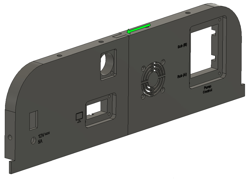
2. Rear panel mounting
Parts
- 2 Dsub 15 connectors
- 6 Dsub Screws
- 16 M3x20
- 4 M4 Nuts
- 16 M3 nuts
- 1 Rs232 Connector
- 2 Wago suuport
- 12 M3x6
- 2 Wago
- 1 DC socket
- 1 switch On Off
- 1 Fuse Holder
- 2 Relays
Tools
- 2 Pliers
- 1 2mm Allen key
Step 1: Big part
- Assemble the two parts,BackLeft.stl & BackRight.stl, by fitting them together following the green arrows.
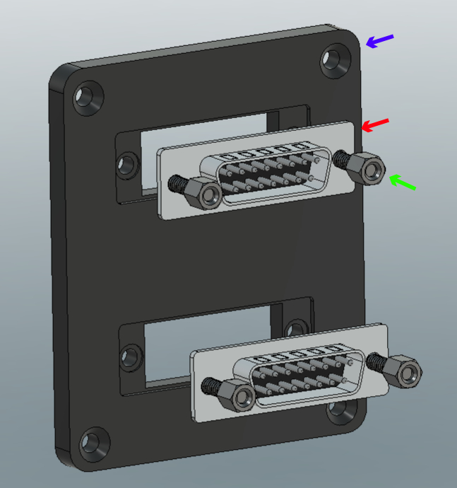
Step 2: Dsub 15 Support
- Take the 3d printed part Support Dsub 15.stl and screw the Dsub 15 connectors (x2) with Dsub Screws (x4) and tighten with two small Pliers .
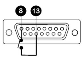
Step 3: First weld
-
Solder two 6 cm yellow wire (0,2 mm²) to pin 8 and 13 of the D-sub 15 Connector and save the solder with Heat Shrink Tubing 1.6 mm sleeve Ø (see pictures). Do not connect the second part of the wire
-
Repeat the same process for the second D-sub 15 Connector.
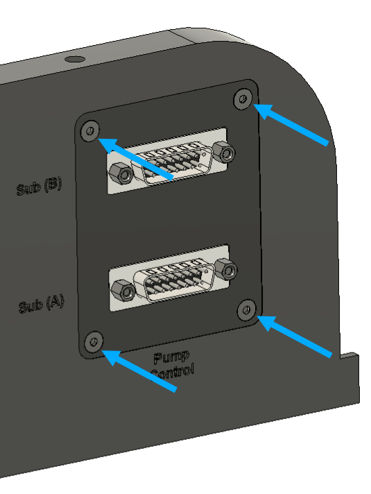
Step 4: Installing Dsub 15 support on de Rear panel
-
Insert the M3x20 (x4) as shown in the picture with the green arrows
-
Put 4 M4 Nuts inside the holes (green arrows) an thighten the screws with a 2mm Allen key.
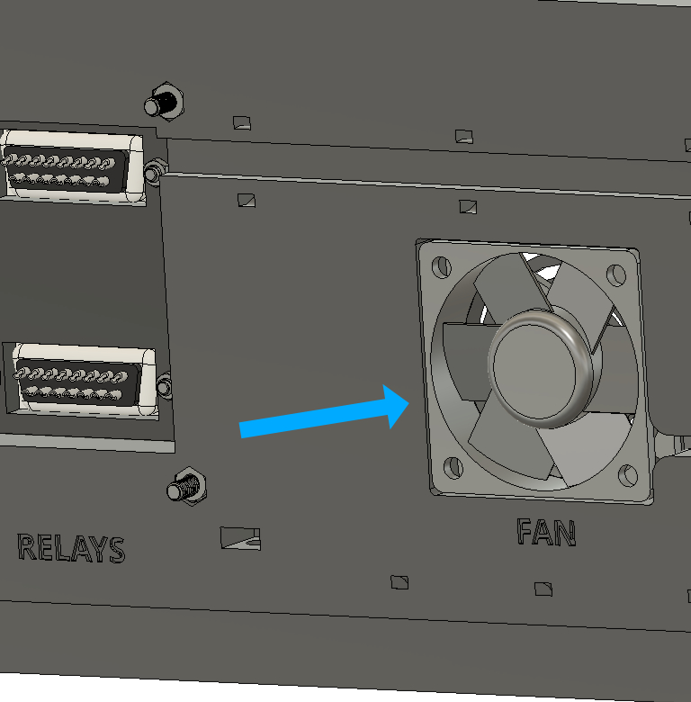
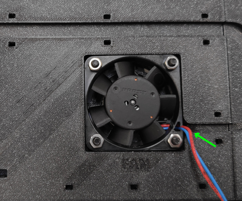
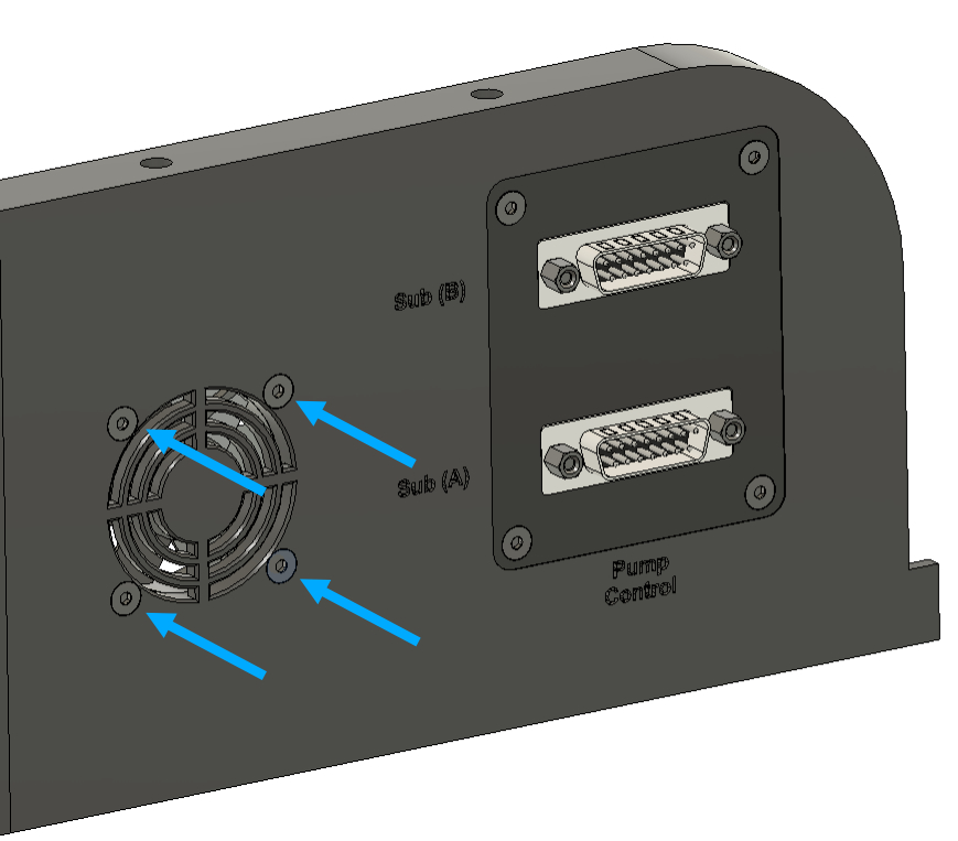
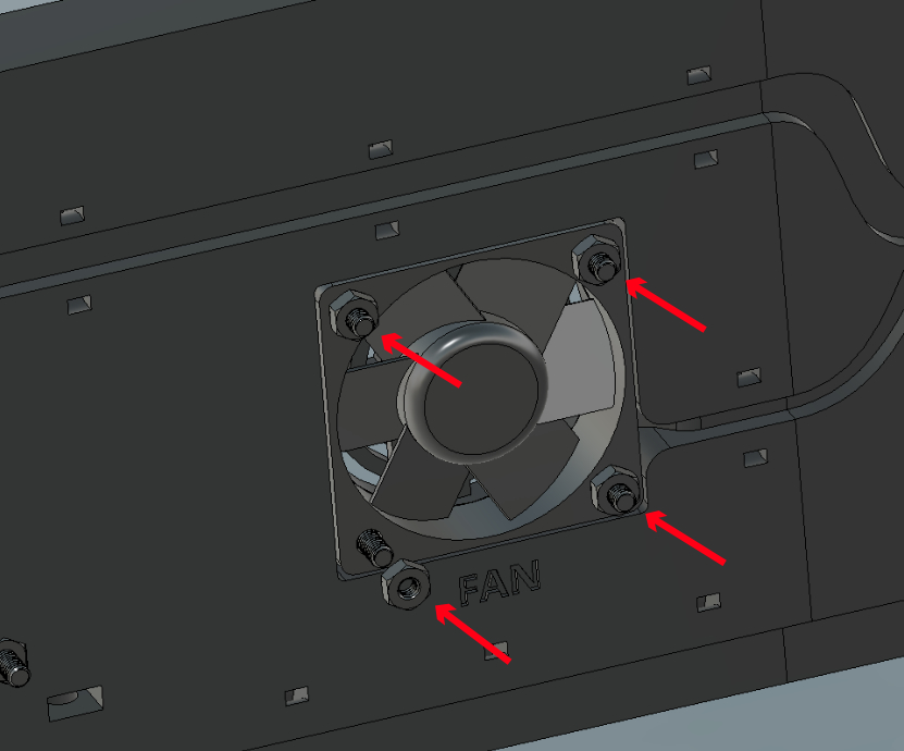
Step 5: Installing Fan
- Insert the fan (blue arrow), make sure that its electrical cables passes through the cable management pipe (green Arrow).
Make sure that the fan sticker is facing the grille on the rear panel.
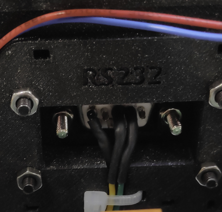
Step 6: Rs232 connector
-
Put the Rs232 Connector on the Rs232 Support.stl (3d printed).
-
Tighten the 2 Dsub Screws using 2 nuts supplied with the screws.
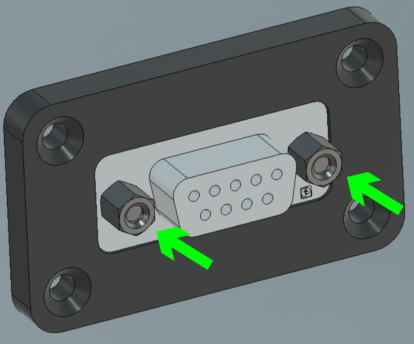
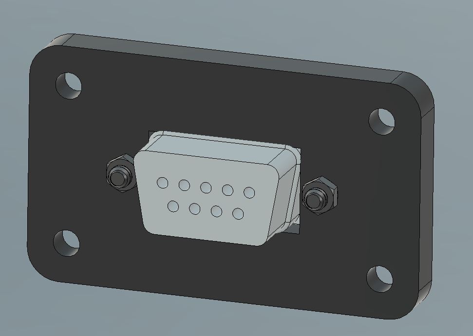
-
Insert the Rs232 support on the rear panel, and use 4 M3x20 and M3 nuts to secure the assembly.
-
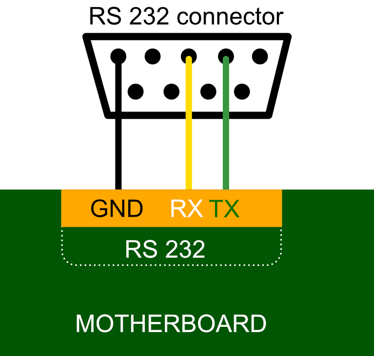
Solder the 3 pins of the connector with 3 different coloured wires (0,2 mm² / 34cm) to easily connect to the board later.
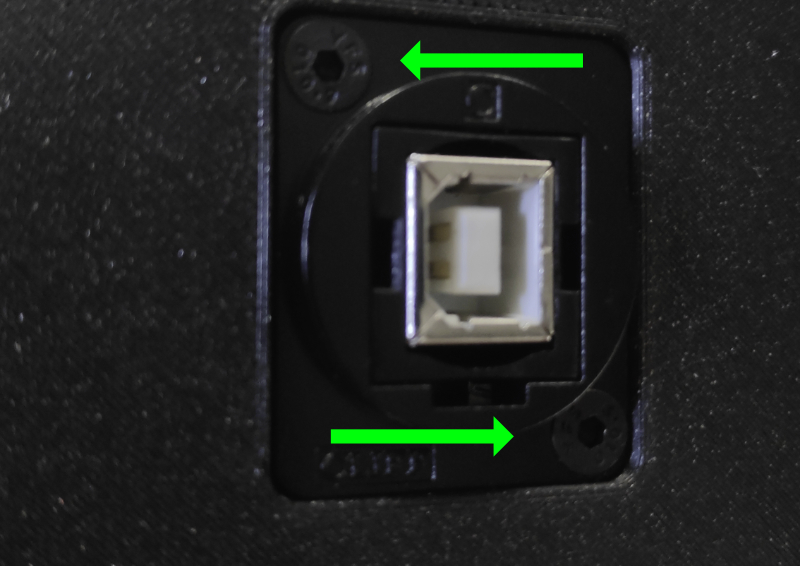
Step 7: USB socket
Step 8: Wago
-
Fix the two Wago suuport (green arrow) with the 2 M3x6 (red arrows) directly into the plastic of the panel.
-
Put the 2 Wago inside the support.
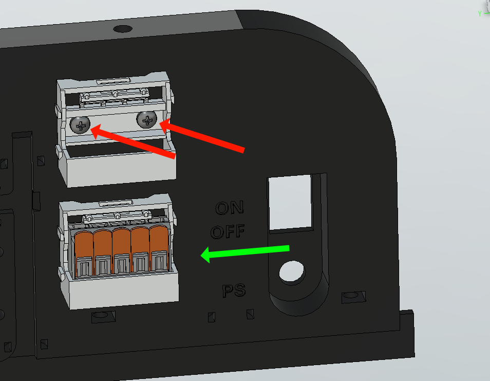
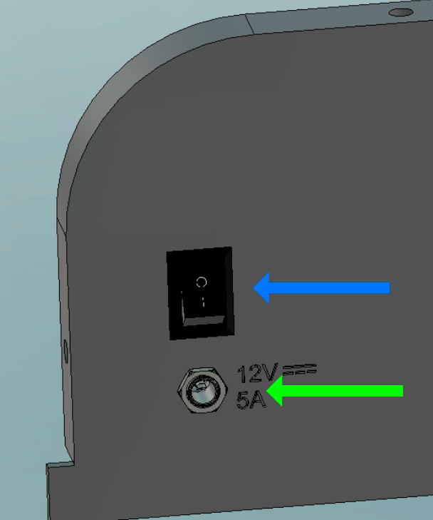
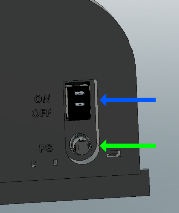
Step 9: Dc socket / Switch ON OFF / Fuse Holder
-
Install the DC socket and thighten it with it's nut (Green arrow).
-
Now insert the switch On Off, just push through the hole (Blue arrow).
-
Finally install the Fuse Holder and tighten it with it's own screw (Pink arrow).
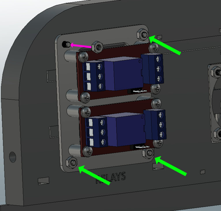
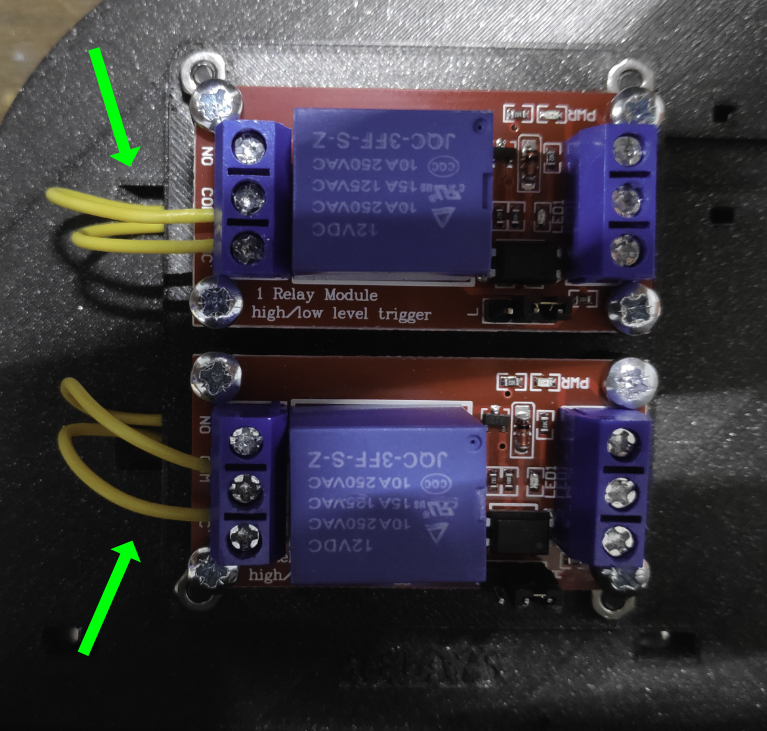
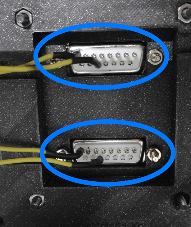
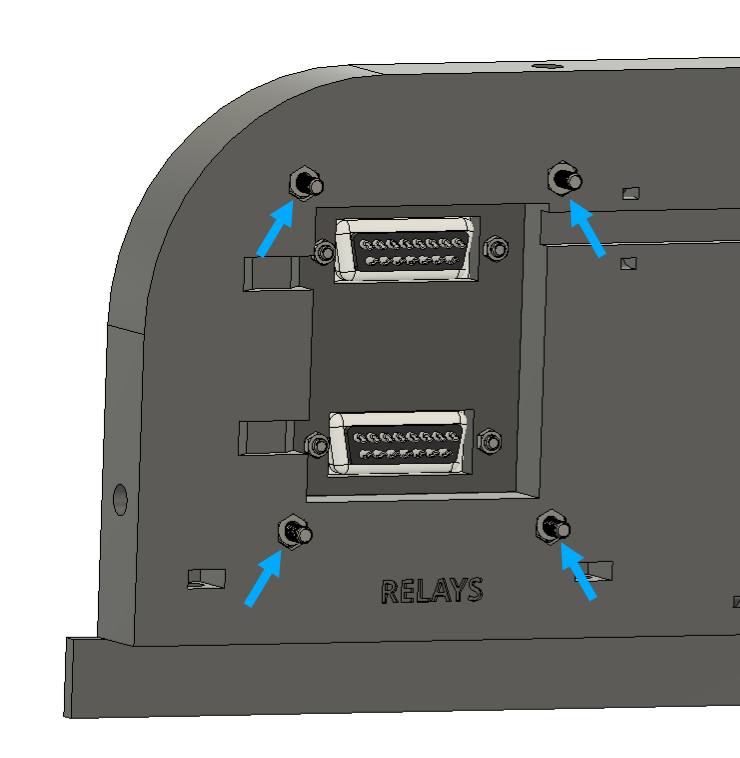
Step 10: Relays
- Fix 2 Relays on the supportRelays.stl with 8 M3x6 and tighten all screws inside the plastic holes.
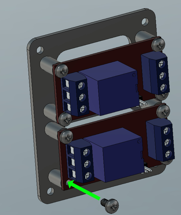
- Use the screws for the D-sub 15 connectors to fix the support relays on the back (see the first picture) and tighten it with M3 nuts (x4).
Make sure the 4 cables are routed through the notches under the relay support on the left (see second pictures).First cable on the COM port & second on the NC . (See electrical diagram)